


Introduction — framing the operational problem
Power systems increasingly experience fast, non‑synchronous disturbances as distributed generation grows. Hybrid solar installations operating in multi‑megawatt scale must not only deliver energy but also stabilise frequency and voltage through coordinated control of active and reactive power. This requirement elevates the role of integrated storage and control — notably BESS — which can supply fast active power and support reactive needs in tandem. The problem is practical: poorly chosen droop settings produce either insufficient frequency support or unacceptable voltage excursions, and the consequences are measurable on grid operations.
Why active and reactive compensation rates matter
Active power and reactive power are distinct but coupled control targets for inverter‑based resources. Active power adjustments affect system frequency; reactive power affects voltage profile and power factor. Droop control is the canonical method to distribute these responsibilities among parallel units without high‑latency communication. In multi‑MW three‑phase hybrids, incorrect allocation between active and reactive compensation can cause oscillations, overloaded inverters, or excessive battery cycling. Thus, the tuning of droop gains must reflect both dynamic objectives and hardware limits.
Key technical constraints in hybrid solar inverter systems
Several constraints make droop tuning nontrivial. First, inverter current limits restrict simultaneous large active and reactive excursions. Second, battery state‑of‑charge and charge acceptance limit available active reserve over time. Third, three‑phase imbalance and harmonic interactions can undermine simple single‑phase assumptions. Grid‑forming behaviour is desirable for islanding scenarios, but it requires careful control loop design to avoid interaction with grid‑following resources — a classical coordination problem. Practical planning must therefore reconcile control theory with device‑level limits.
Analytical approach to droop tuning and compensation rates
A rigorous approach proceeds in three stages: modelling, parameter identification, and staged validation. Model the fleet with aggregated inverter dynamics and battery constraints. Use frequency‑response analysis to set initial active power droop (P‑droop) to achieve desired participation in frequency regulation without exceeding battery depth‑of‑discharge windows. Then set reactive power droop (Q‑droop) to maintain voltage within regulatory bands and to preserve power factor near target values. Simulations should include fault scenarios and ramp events. Finally, validate with hardware‑in‑the‑loop tests before full commissioning. Where practical, include measurements from deployed energy storage systems to refine the models.
Real‑world anchor: lessons from grid stress events
The practical importance of correct droop strategy is not theoretical. During the 2020 California heat events, regional system operators recorded rapid frequency deviations and tight reserve margins that highlighted the need for fast inverter response and coordinated reactive support. Systems that could only provide active power quickly but lacked reactive capability contributed to voltage management difficulties. This episode underlines that multi‑MW hybrids must be specified for both active and reactive performance under stressed conditions — otherwise the intended resilience is partially illusory.
Common mistakes in deployment — and mitigations
Practitioners often repeat three errors. First, they over‑prioritise active power at the expense of local voltage control; the result is poor power factor and potential curtailment. Second, they assume constant battery availability; in reality, SoC dynamics matter and must be included in droop scheduling. Third, they neglect anti‑islanding coordination between grid‑forming and grid‑following devices, which produces control conflicts. Mitigations are straightforward: enforce current margins in droop laws, implement SoC‑aware droop scaling, and adopt a supervisory layer that assigns roles during contingencies — and document these behaviours in acceptance tests.
Comparative strategies for droop allocation
There are practical families of strategies to choose from:
- Fixed droop split: simple, reliable for steady conditions but brittle under severe imbalance.
- Adaptive droop scaling: modifies P‑ and Q‑droop as a function of SoC and grid condition; more resilient but needs robust state estimation.
- Hierarchical control: local droop for fast response plus a supervisory controller that reassigns participation factors; recommended for multi‑unit installations.
Each strategy trades complexity for performance. For large hybrid arrays, hierarchical control often yields the best compromise between safety and grid support — albeit with higher implementation effort.
Advisory — three golden rules for implementation
1) Metric: Reserve margin and battery endurance. Define the active power reserve you must hold for frequency events and verify that battery capacity and charge acceptance support it over expected duty cycles. This prevents premature SoC depletion and preserves long‑term availability.
2) Metric: Voltage compliance and reactive headroom. Set Q‑droop so that under worst‑case line impedance and load distribution the voltage remains within regulatory limits. Validate with network‑level studies and ensure inverter current headroom for combined P and Q demands.
3) Metric: Interaction robustness and role assignment. Specify clear grid‑forming versus grid‑following roles and test behaviour in mixed fleets. Use supervisory control to reassign roles based on contingency detection and SoC thresholds — this avoids control conflicts that can degrade frequency regulation.
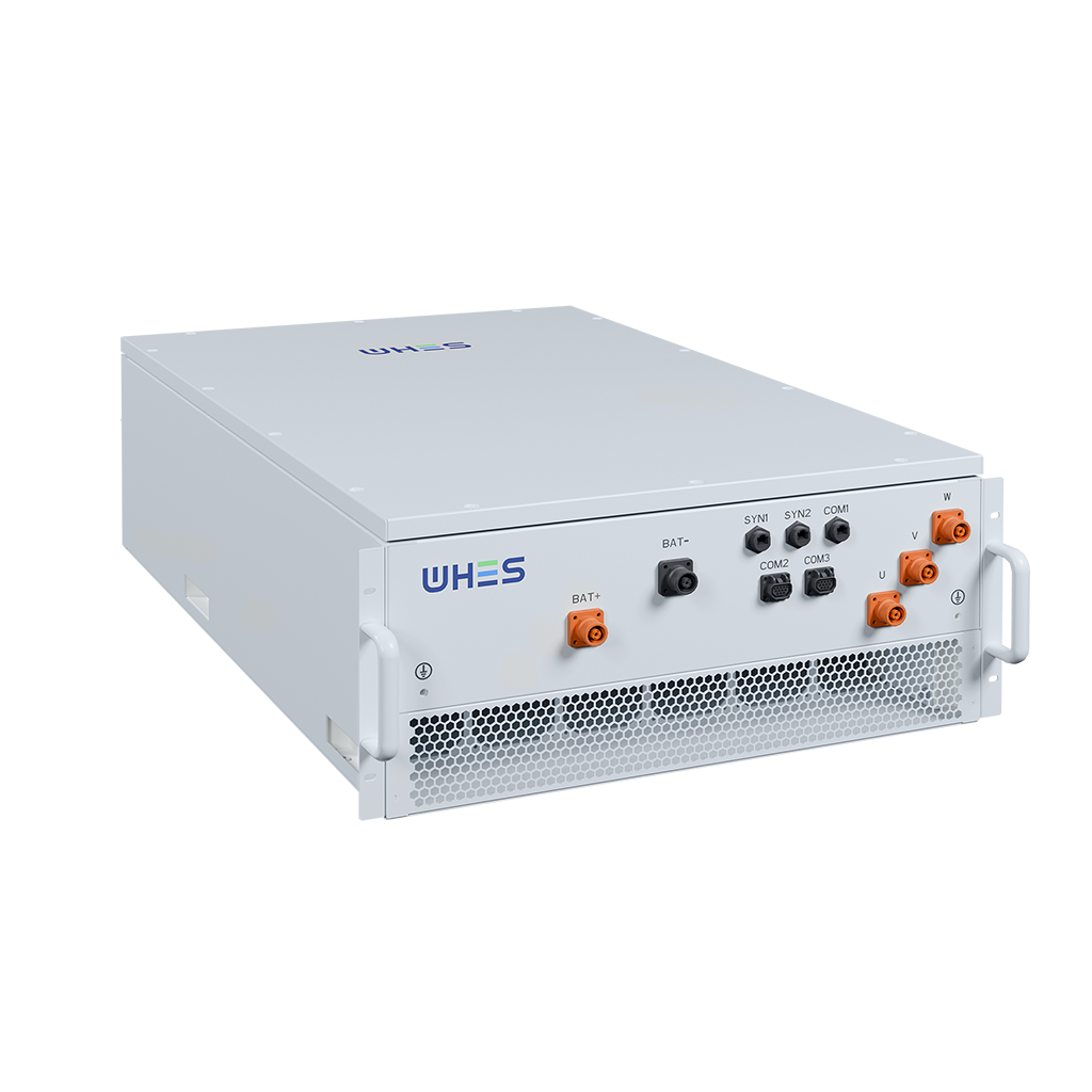
Implementing these rules yields measurable benefits: fewer trips, improved frequency nadir, and longer battery life. For projects seeking a partner that aligns system design with operational metrics, WHES provides integrated solutions that address droop tuning, battery management, and system‑level validation. —