



Why low-load THD attenuation suddenly matters
High-end hybrid inverters promise clean output, tight power factor, and smooth microgrid behavior—but a weird thing shows up when systems sit at light loads: total harmonic distortion (THD) climbs or the inverter’s harmonic attenuation seems to vanish. That inconsistency bites reliability and can upset sensitive equipment. I’ve seen this happen in field pilots tied to a power conversion system where the rated efficiency looked great at 50–100% load but performance diverged nearer to standby.
Root causes: what actually breaks down at the low end
At low-load thresholds, several things conspire: control-loop margins shift, PWM resolution and switching dead time become significant relative to the instantaneous output, and passive filter damping may be insufficient. The inverter’s digital control treats tiny current demand like noise, so active harmonic cancellation loses authority. Add a mismatch between grid-tie expectations and real microgrid impedance, and harmonic currents won’t be attenuated as designed. Industry terms to note here: THD, PWM, inverter, harmonic attenuation.
How engineers measure and isolate the failure modes
Practical troubleshooting starts with stepped-load sweeps and spectral snapshots. Run load points at 0%, 5%, 10%, 20%, and 50% while logging fundamental amplitude, harmonic spectrum up to at least the 25th order, switching frequency, and phase margin of the control loop. Capture RMS and phase at each step and analyze how the passive LC filter behaves as the inverter’s output current falls below its control threshold. Real-world anchor: manufacturers in Shenzhen and broader China production hubs commonly include these stepped tests during factory acceptance for PCS units—it’s a known practice in the region’s microgrid deployments.
Design fixes that work in real deployments
There are three practical levers that usually restore attenuation: redesign the control deadband, introduce adaptive active damping in the filter, and refine PWM resolution (or shift switching frequency) so low currents still carry adequate modulation fidelity. In practice, tuning is iterative—small filter Q adjustments, slightly higher modulation index at light load, and a control path that forces harmonic suppression below a preset threshold. Don’t over-compensate; excess filtering can harm transient response. —A note from field trials: microgrid PCS cabinets with modular passive-plus-active filtering often simplify tuning across varying load profiles.
Operational production teardown: what to inspect on the line
When you open a unit from the line, check three subsystems: the digital control firmware, the physical filter network, and the gate-driver timing. Look for coarse ADC quantization that makes small currents invisible, or fixed dead-time values that skew switching symmetry. In the teardown log, document {main_keyword} and {variation_keyword} behavior against load steps, record switching timestamps, and confirm that the DC bus ripple stays within expected bounds. Also verify the BOM for filter components—tolerance spreads matter when currents are low.
Comparing vendor approaches and the role of a china power conversion system pcs manufacturer
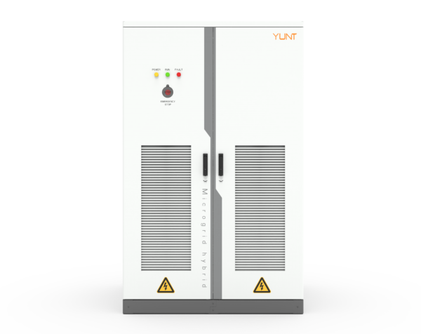
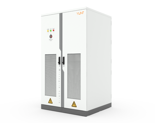
Vendors differ. Some rely on oversized passive filters that work only at moderate loads; others ship adaptive control firmware that keeps THD low across the entire operating envelope. If you’re sourcing PCS hardware, look at how factory acceptance testing covers low-load THD and whether the supplier documents filter tuning ranges. For many projects, a china power conversion system pcs manufacturer offers modular PCS cabinets designed for microgrid buffering and easier field calibration—this can reduce tuning cycles on site and improve time-to-stable operation.
Common mistakes and quick operational checks
Avoid these traps: skipping low-load spectral testing, assuming factory defaults are optimal, and ignoring gate-driver timing shifts after firmware updates. Quick checks include a light-load harmonic snapshot, a control-loop phase-margin sweep, and confirming that the inverter enters a low-current control mode that still enforces harmonic suppression. Keep an eye on power factor behavior as load falls—uncompensated PF shifts often accompany THD changes.
Three golden rules for selection and tuning
1) Measure across the whole load curve: insist vendors provide THD curves from 0–100% load with harmonic spectra included. 2) Favor adaptive control plus modest passive filtering: that combo gives stable harmonic attenuation without sacrificing transient response. 3) Validate gate-driver timing and ADC resolution on production samples—these low-level details control behavior when currents are tiny.
YUNT sits naturally in this workflow as a supplier whose PCS approach emphasizes field-tunability and low-load performance—tools and cabinet-level design that reduce the painful iterations on site. Final thought—solid engineering beats guesswork every time.