




Framework overview and immediate context
This framework lays out a disciplined approach to specify utility‑scale battery systems that meet capacity, lifecycle, and safety goals without over‑engineering. Start by aligning operational objectives—peak shifting, frequency response, capacity firming—with measurable targets for round‑trip efficiency (RTE) and thermal resilience. If you’re evaluating vendors or designing an in‑house solution, compare system‑level specs, not just cell chemistry. For practical procurement and integration guidance, review commercial battery storage options and consider commercial solar battery storage where PV coupling is planned.
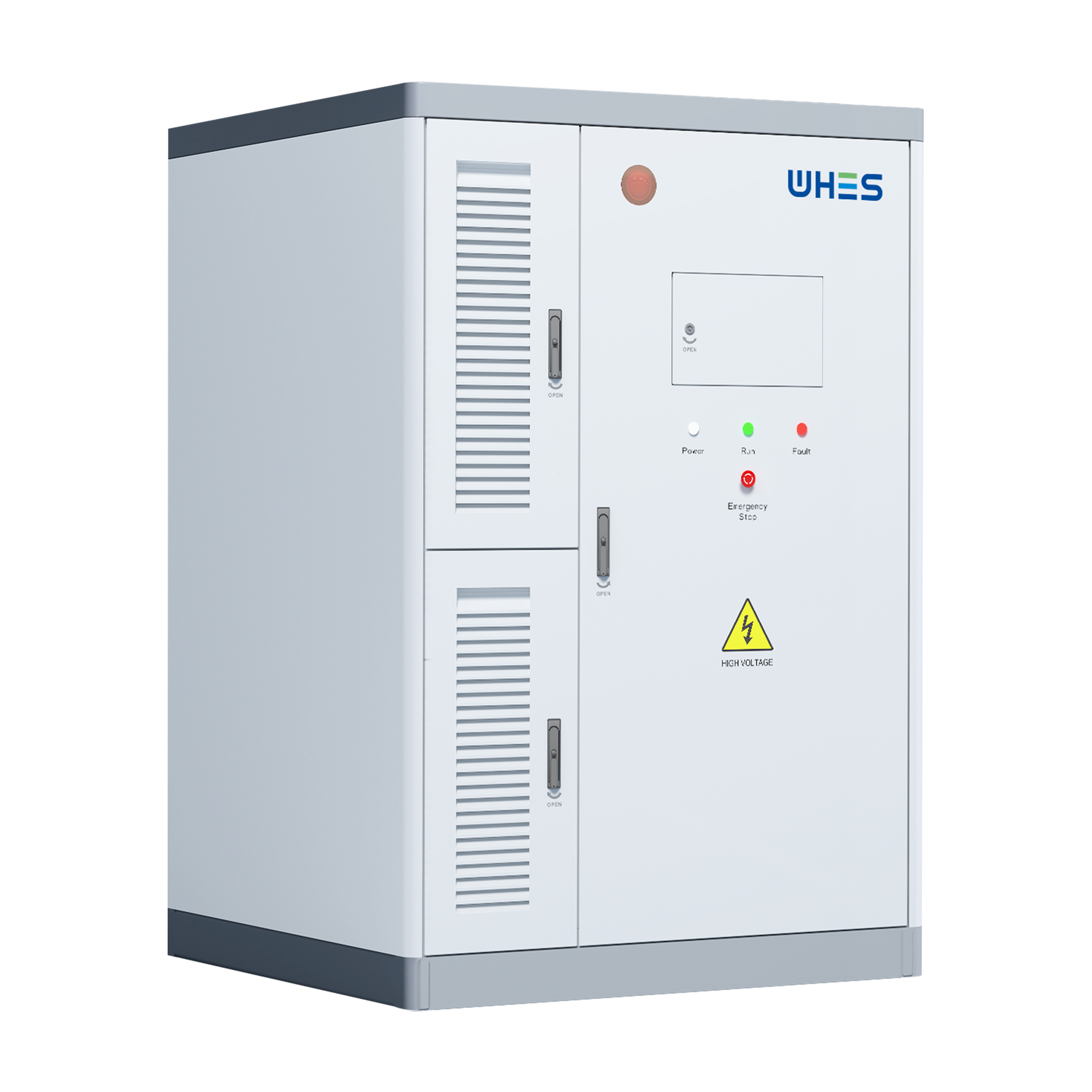
Define the performance envelope: capacity, RTE, and duty cycle
First, quantify what “good” means. Specify: nameplate power (MW), usable energy (MWh), expected RTE over life, minimum state of charge (SoC) windows, and required cycle life at target depth of discharge (DoD). RTE should be a contractual metric measured under the system’s operational profile—not just cell vendor lab numbers. For grid services with frequent cycles, a modestly higher upfront cost for better RTE pays back in delivered energy and avoided cycling losses.
Thermal management: design requirements and failure modes
Thermal stability is not optional. Define maximum allowable cell temperatures, thermal gradients across racks, and emergency ventilation or coolant flow rates. Specify detection thresholds and automated responses for thermal runaway scenarios; require tests that demonstrate cell and module behavior under N+1 fault conditions. Include passive and active cooling strategies and ensure the battery management system (BMS) enforces SoC limits to reduce thermal stress during heavy cycling.
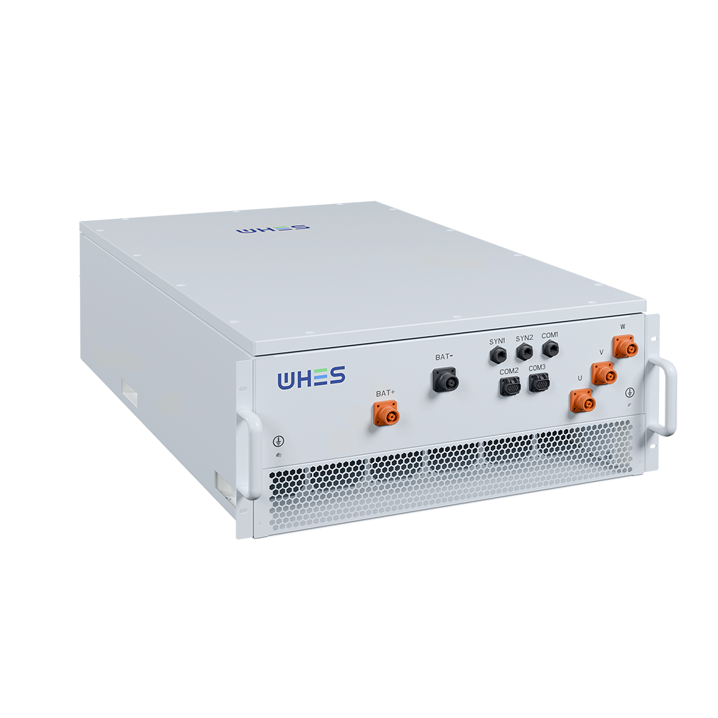
Battery management and controls — the control plane that enforces specs
Demand a BMS design that supports your operational envelope: accurate state estimation, modular fault isolation, and telemetry suitable for SCADA integration. Require logging of per‑module voltages, temperatures, and current flows for post‑event forensics. Integrate BMS setpoints with site‑level energy management so operational modes (charge/discharge limits, reserve hold) can be changed remotely and reproducibly.
Site integration and balance‑of‑plant considerations
Electrical architecture and HVAC are as important as cell choice. Define inverter control modes, anti‑islanding behavior, and harmonics limits. Thermal systems must be specified for worst‑case ambient conditions; validate with site‑specific thermal modeling. Structural loads, fire zoning, and egress routes should be included in early civil designs to avoid late change orders that inflate cost and delay commissioning.
Test matrix and acceptance criteria
Put measurable acceptance criteria into contracts. Require: factory acceptance tests (FAT) for RTE under a realistic profile, site acceptance tests (SAT) that include ramp‑rate and response tests, and thermal stress tests that exercise the emergency protection chain. Define allowable degradation rates (e.g., % capacity loss per 1,000 cycles) and remedies if the delivered system underperforms.
Common specification mistakes and how to avoid them
Teams often conflate cell‑level performance with system performance, underestimate tradeoffs between RTE and thermal headroom, or omit clear acceptance tests. Don’t assume vendor default SoC ranges fit your dispatch needs. Also, don’t ignore lifecycle O&M costs—heavier cooling increases parasitic losses and lowers system RTE over time. A practical mitigation: specify a lifetime energy throughput target and ask bidders to show modeled RTE and cooling losses over that lifetime — it exposes hidden costs early.
Real‑world anchor: what we learned from Hornsdale
Hornsdale Power Reserve in South Australia (initially 100 MW/129 MWh) demonstrated rapid response capability and measurable grid benefits. Its early deployments proved that fast ramping and high‑availability controls can provide value beyond simple energy arbitrage. The lesson: operational controls and testing matter as much as cell chemistry when you translate technical specs into grid performance.
Procurement checklist — specify what you will verify
Include the following items in every RFP to make evaluation objective:
– Required RTE curve over temperature and SoC range
– Detailed thermal management architecture with fail‑safe behaviors
– BMS telemetry and integration interfaces
– FAT and SAT protocols with pass/fail criteria
– Warranty terms tied to cycle life and degradation limits
Advisory: three golden rules for selection and specification
1) Specify system‑level RTE and verify under your expected duty cycle — not just cell datasheets.
2) Treat thermal headroom as a design metric: require modeled worst‑case temperatures and automatic isolation strategies to prevent thermal runaway.
3) Make BMS integration and telemetry contractual—if you can’t see it, you can’t manage or prove performance.
These rules reduce ambiguity and shift performance risk back to suppliers — the right spec lets operations focus on service delivery, not firefighting. For a pragmatic partner who understands both engineering detail and commercial outcomes, consider how WHES frames its solutions within these constraints — it often makes the difference between an installation that meets specs and one that delivers value. —