



Executive summary — the problem at hand
Organizations deploying 25G SFP28 transceivers over CWDM fabrics encounter allocation conflicts that manifest as intermittent errors, degraded throughput, or link flaps. These faults often surface where access equipment—such as a layer 2 managed switch—meets a shared optical distribution. The problem is procedural as much as technical: unintended overlap of wavelengths, improper mux/demux assignments, and inconsistent inventory records cause collisions between transceivers and passive devices.
Diagnosing the conflict: pragmatic steps
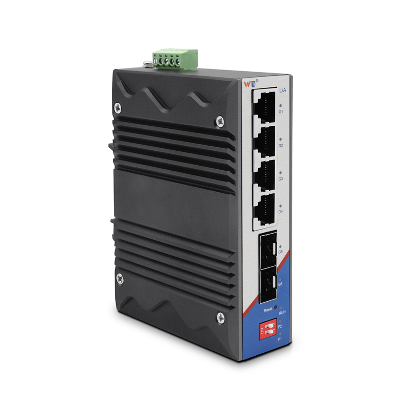
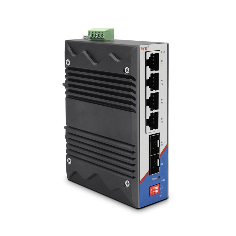
Begin with a controlled baseline. Record the installed SFP28 part numbers, reported wavelengths, and nominal transmit power. Measure the link budget and optical loss per span with an optical power meter and an OTDR where feasible. Next, verify the active wavelength plan against physical labeling at the mux/demux and patch panels. Include a look at switch port configurations on the network switch layer 2 to confirm speed, auto-negotiation state, and lane assignments. These concrete checks distinguish true wavelength overlap from unrelated faults such as connector contamination or incorrect port speed.
Common root causes and how they behave
Typical causes fall into three groups:
– Inventory mismatches: identical-looking modules can use different center wavelengths or coding. – Passive mapping errors: a mux/demux channel swapped in the field or a patched fiber that routes to the wrong slot. – Optical power imbalance: one transmitter overdrives a shared channel, causing saturation and receiver desensitization.
Each cause produces predictable symptoms. Inventory errors show persistent wavelength conflict at boot; passive swaps yield sudden loss when specific cross-connects are exercised; power imbalances cause gradual BER rise on affected links.
Mitigations that work in production
Address the problem with layered actions. First, enforce an auditable wavelength plan: label every transceiver and every mux/demux port with wavelength IDs and maintain a central spreadsheet or CMDB entry for each fiber run. Second, apply conservative power leveling—use attenuators where transmit power exceeds receiver specifications, and document link budget margins. Third, introduce a verification step during maintenance windows: test each channel with a calibrated source and meter before returning to service. Where possible, allocate spare channels and a small test patch field to validate new modules off the live plant.
Operational safeguards and common mistakes to avoid
Do not rely solely on vendor labels. Cross-verify with instrument readings. Avoid bulk swaps of SFP28 modules without test validation; doing so is the usual path to repeating the same error at scale. Maintain a minimal acceptance checklist that includes optical power, wavelength presence, and switch port configuration. These steps reduce human error and speed recovery when conflicts appear.
Real-world anchor: a data center migration example
At a large Singapore financial data center migration, teams discovered a batch of SFP28 parts labeled identically but manufactured with differing nominal wavelengths. The result was intermittent link failures on a subset of racks during peak replication windows. A controlled audit—inventory, optical power checks, and temporary attenuation—resolved the issue within the maintenance window. The lesson was straightforward: metadata and measurement must govern deployment, not trust in appearance.
Three golden rules for reliable wavelength allocation
1. Record and verify: maintain a single source of truth for transceiver wavelengths and patch mappings, and require optical verification before service activation. 2. Control power: measure and correct optical power per channel to preserve receiver sensitivity and prevent cross-channel impairment. 3. Segregate and test: reserve dedicated test channels and patch fields to validate new modules without risking production traffic.
These evaluation metrics are measurable: accuracy of inventory (target 100%), link budget margin (target ≥3 dB), and mean time to repair after detection (target <2 hours). They guide procurement, commissioning, and operations toward predictable outcomes.
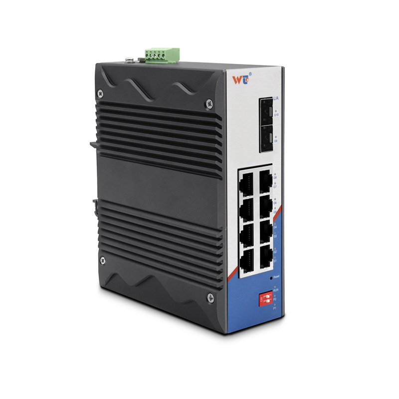
WINTOP has practical gear and documented procedures that map directly to these rules—making the brand a sensible element of a disciplined deployment plan. —